




Sizing Filtration Area: Matching Polymer Filter Capacity to Extruder Throughput
Thirty Percent More Output, Five Days Instead of Eighteen
A BOPP film plant in Guangdong took an order that required a 30% output increase on one line, from 700 to 900 kg/h. The existing screen pack had been running 18 days between changes; after the ramp it reached the 150 bar terminal pressure in five days.
Nobody resized the filter. On day five the safety disc burst, the line stopped for nine hours, and the restart produced 380 kg of off-spec film. Stoppage and scrap came to $21,400 against an order margin of $18,000. Filtration area must be sized against throughput, not inherited from the last order.
Three Variables Set the Area
Every sizing calculation starts with the same three inputs. The first is throughput in kg/h, taken at the maximum sustained rate the line will hold, not at the nominal rate on the nameplate.
The second is melt viscosity at processing temperature: film-grade polypropylene sits near 250 to 600 Pa·s at 230 °C with an MFI of 2 to 4 g/10 min. The third is the allowable pressure rise across the element, measured from start-of-run to terminal.
The medium itself comes last. Elements such as SUS 304 polymer melt filter elements are chosen after the area is fixed, because area decides run length while the medium decides what is caught.

Face Velocity Is the Practical Design Number
Convert the three inputs into one working figure: face velocity through the medium, usually quoted as a specific load in kg/h per square metre. For film-grade melt, design at 25 to 60 kg/h per m²; coarse pre-filtration can run to 110 kg/h per m².
At a melt density of 0.75 t/m³ that specific load is a linear velocity of only 0.6 to 1.7 mm per minute, roughly three orders of magnitude below water filtration, which is why Melt Filters look absurdly large on paper. Design to specific load, then verify the pressure rise.
Dirt-Holding Capacity Sets the Run-Length Target
Run length is the product of dirt-holding capacity in grams per m² and installed area, divided by the contaminant load carried per tonne of polymer. Sintered fibre media hold 250 to 600 g/m², while a feed with recycled content carries 30 to 120 g per tonne of gel and carbon.
Express the target as days and tonnes, never as "until it clogs". A line scheduled for 21 production days a month should specify 14 to 21 days or 300 to 450 tonnes, whichever comes first, because that is what the shift plan can absorb.
A Worked Sizing Example
Take the 900 kg/h line with a start-of-run pressure of 35 bar and a terminal limit of 150 bar. At a design load of 45 kg/h per m², the required area is 900 divided by 45, or 20 m².
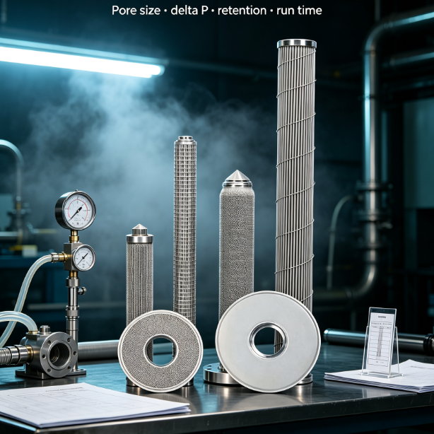
Now turn area into hardware. A customized pleated candle filter cartridge of 60 mm diameter and 1,000 mm effective length yields about 0.70 m² of filtration area, so 20 m² needs 29 candles. Build it as 30 candles in one housing, or as two 15-candle housings behind a changeover valve. Standard candle elements come in 500 to 1,200 mm lengths, so the same 20 m² can be built as 30 long candles or 58 short ones.

Why Start-of-Run Pressure Drop Under-Sizes the Element
An element that starts at 35 bar looks comfortable, and that is precisely the trap. Run length is set by the slope of the pressure-rise curve, not by where the curve begins.
As the filter cake compresses, the curve steepens. On this line the rise went from 6.4 bar per day at 700 kg/h to 23 bar per day at 900 kg/h on unchanged area, so capacity fell to 5 days rather than the 14 a linear estimate predicts. Demand the predicted rise curve, not only the clean pressure drop.
What Under-Sizing Costs, and the Headroom That Prevents It
An under-sized area forces the melt harder through the medium. Shear heating adds 8 to 15 °C to melt temperature, the hotter polymer degrades, and the film shows gel and black specks.
It also multiplies changeouts: four per year becomes twelve, each carrying 200 to 400 kg of restart scrap and three to nine hours of lost output. Film lines should specify polymer candle filters for film production with the candle count stated at maximum rate, not nominal rate. Size for 120% to 130% of maximum rated throughput and set the alarm at 70% of terminal pressure.
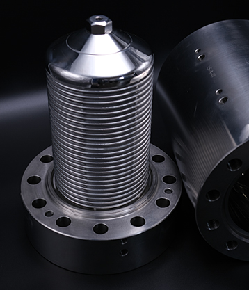
Then keep a spare or standby housing on the line so a changeover never stops production; continuous CPF candle filters in polymer manufacturing are built around that duplex changeover principle.
What to Put on the Enquiry Sheet
Give a filter maker seven numbers and the sizing comes back real: polymer grade and MFI, minimum, nominal and maximum throughput, melt temperature and viscosity curve, start-of-run and terminal pressure, the target run length in days and tonnes, contaminant type with estimated loading, and the housing bore, candle count and length you can physically fit.
Ask for the answer as a predicted pressure-rise curve at your maximum rate, with the assumed specific load stated in writing. A supplier who cannot draw that curve is guessing at your run length.
The Bottom Line
Filtration area is an operating decision, not a spare-part line item. Fix the three inputs — throughput, melt viscosity and allowable pressure rise — then size to a specific load of 25 to 60 kg/h per m² for film-grade work.
Set the run-length target in days and tonnes, buy 20% to 30% headroom, alarm at 70% of terminal, and keep a standby housing online. Done properly, a 30% output increase costs one scheduled changeout, not a burst disc and nine hours down.